Industrial Measurement Technology
Industrial measurement technology enables the precise acquisition of spatial data from objects. Using modern measuring systems, three-dimensional coordinate points are captured to create exact digital models. This technology is crucial for quality assurance and the development of complex products, as it provides detailed information about the geometry and dimensions of an object.
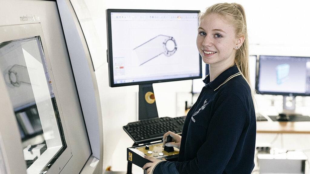
3D Measurement for High-Resolution Analysis
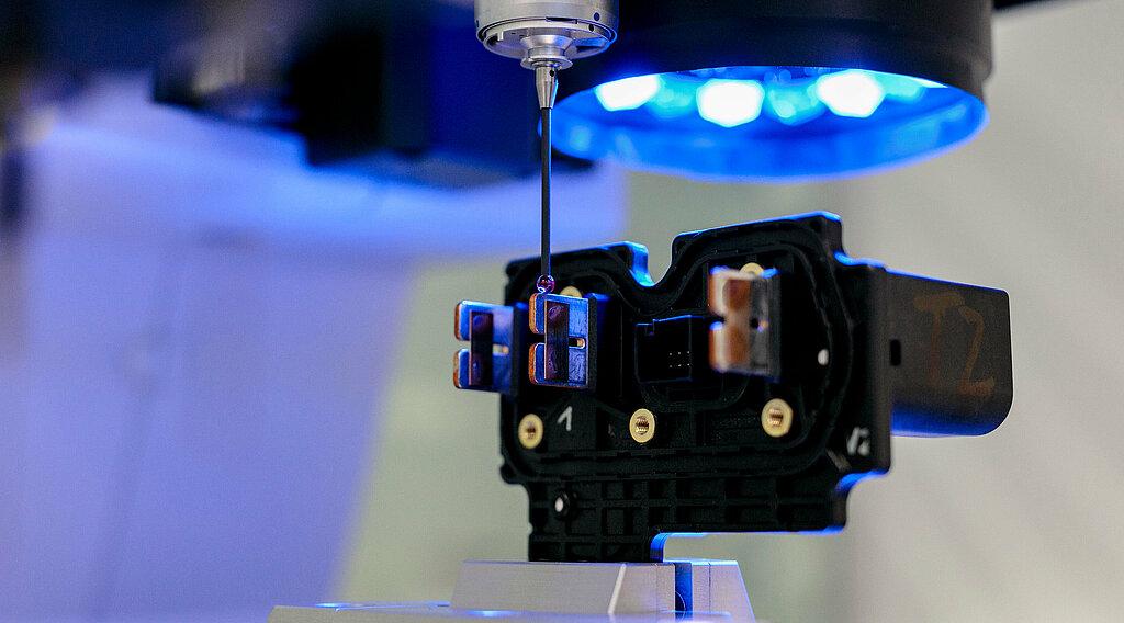
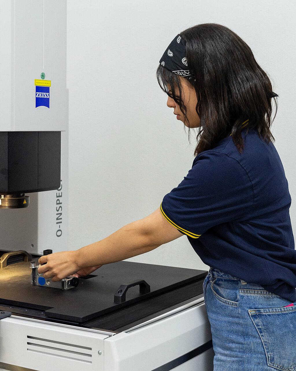
The measurement process at Hirschmann Automotive offers a wide range of evaluation and documentation options. Both optical and tactile measuring methods are available, enabling precise dimensional measurement of components through various measuring strategies and component orientations. The findings can be documented in multiple formats, ensuring detailed analysis and traceability of the measurement results.
Processing this 3D data involves analyzing and interpreting the captured points to ensure that the product meets the given specifications. This comprehensive information enables accurate defect detection, improved manufacturing accuracy and efficient optimization of the design process.
3D Coordinate Measuring Machines
The Hirschmann Automotive measuring laboratory is accredited according to DIN EN ISO / IEC 17025 for the following internal test procedure for optical-tactile measurements: HA-PV-QLM-00001_V02 – the test procedure for determining geometric dimensional and form deviations on components made of various materials, as well as for performing and documenting tests using multisensor measuring devices.
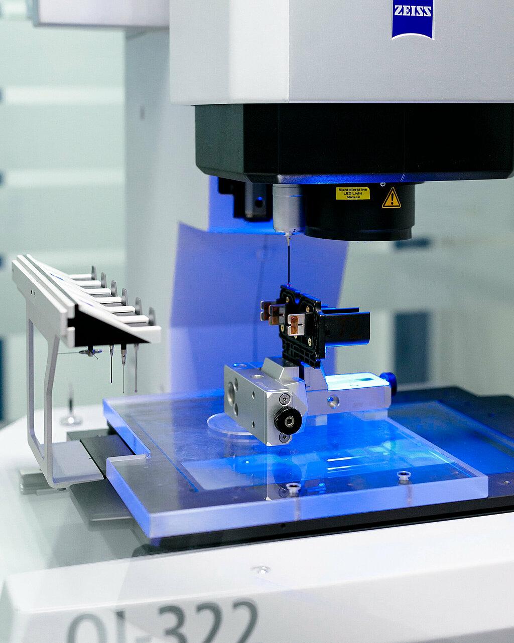
ZEISS / O-Inspect 322
Test Equipment Number: Q-50-12812
Calibration Frequency / Month: 12 months, maintenance 12 months
Spezification:
Measurement Range: 300x300x200mm
Resolution / mm: 0,00001mm
System Accuracy (manufacturer’s data at 20°C): MPE = 2,4 μm + (L/200) (optical and tactile)
Standard: according to VDI/VDE 2617, DIN EN ISO 10360
Possible Applications: 3D metrology optical and tactile, scan function, comparsion with 3D Model
Special Accessories, Software, Clamping Options: integrated damping system, integrated temperature sensor, automatic sensor replacement, 8-segment ring light, 12x zoom
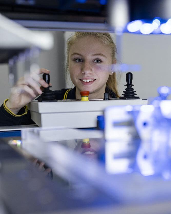
ZEISS / O-Inspect 442
Test Equipment Number: Q-50-14349
Calibration Frequency / Month: 12 months, maintenance 12 months
Spezification:
Measurement Range: 400x400x200mm
Resolution / mm: 0,00001mm
System Accuracy (manufacturer’s data at 20°C): MPE = 2,4 μm + (L/200) (optical and tactile)
Standard: according to VDI/VDE 2617, DIN EN ISO 10360
Possible Applications: 3D metrology optical and tactile, scan function, comparsion with 3D Model
Special Accessories, Software, Clamping Options: integrated damping system, integrated temperature sensor, automatic sensor replacement, 8-segment ring light, 12x zoom
ZEISS / O-Inspect 442
Test Equipment Number: Q-50-12811
Calibration Frequency / Month: 12 months, maintenance 12 months
Spezification:
Measurement Range: 400x400x200mm
Resolution / mm: 0,00001mm
System Accuracy (manufacturer’s data at 20°C): MPE = 2,4 μm + (L/200) (optical and tactile)
Standard: according to VDI/VDE 2617, DIN EN ISO 10360
Possible Applications: 3D metrology optical and tactile, scan function, comparsion with 3D Model
Special Accessories, Software, Clamping Options: integrated damping system, integrated temperature sensor, automatic sensor replacement, 8-segment ring light, 12x zoom, white light sensor
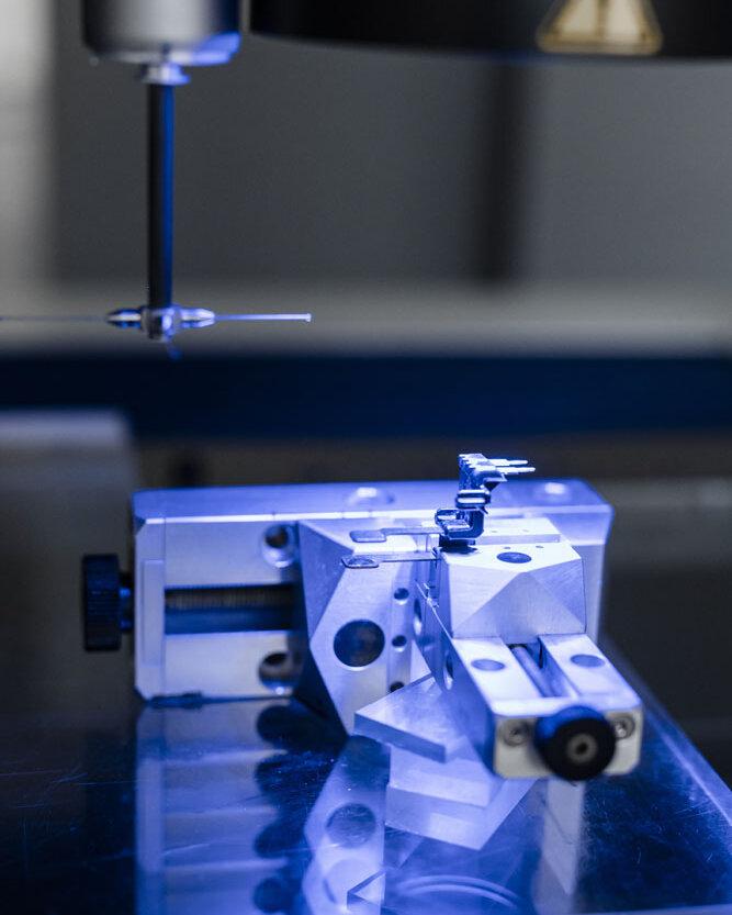
ZEISS / O-Inspect 543
Test Equipment Number: Q-60-17023
Calibration Frequency / Month: 12 months, maintenance 12 months
Spezification:
Measurement Range: 500x400x300mm
Resolution / mm: 0,00001mm
System Accuracy (manufacturer’s data at 20°C): MPE = 1,6 μm + (L/250) (optical and tactile)
Standard: according to VDI/VDE 2617, DIN EN ISO 10360
Possible Applications: 3D metrology optical and tactile, scan function, comparsion with 3D Model
Special Accessories, Software, Clamping Options: integrated damping system, integrated temperature sensor, automatic sensor replacement, 8-segment ring light, 12x zoom
Comprehensive Documentation for Detailed Analysis
The 3D measurement processes at Hirschmann Automotive offer a wide range of evaluation and documentation options. The processing of 3D data includes the analysis and interpretation of the captured points to ensure that the product meets the given specifications. This comprehensive information enables accurate defect detection, improved manufacturing accuracy and efficient optimization of the design process.
Computer Tomography (CT) Facilities
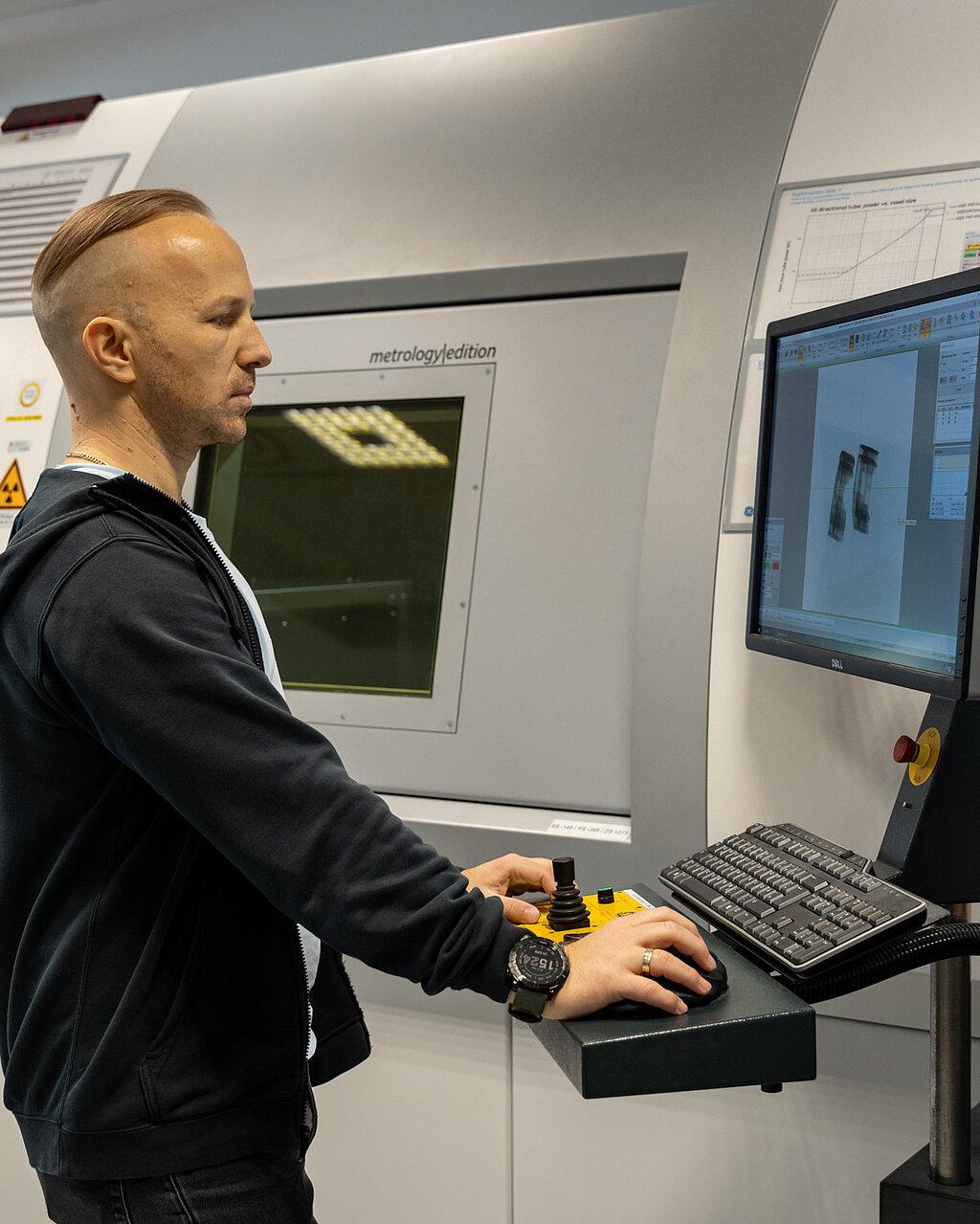
Waygate / Vtomex m 240
Test Equipment Number: Q-60-15495
Calibration Frequency / Month: 12 months, maintenance 6 months
Spezification: This advanced computed tomography system includes a 240kV unipolar X-ray tube with longlife filament technology, a 16-inch digital detector with 4 Megapixels for excellent contrast resolution, and 5-axis sample manipulation on a granite base. A temperature-stabilized radiation protection cabin and anti-vibration system ensure stable measurement conditions.
Possible Applications: 3D metrology, lunker analyses, wall thickness analyses, target-actual comparson, defect analyses, fiber composite analyses
Special Accessories, Software, Clamping Options: phoenix datos x3D CT acquisition and reconstruction Software, 5 workplaces with VG-StudioMax vor evaluation of the scan data
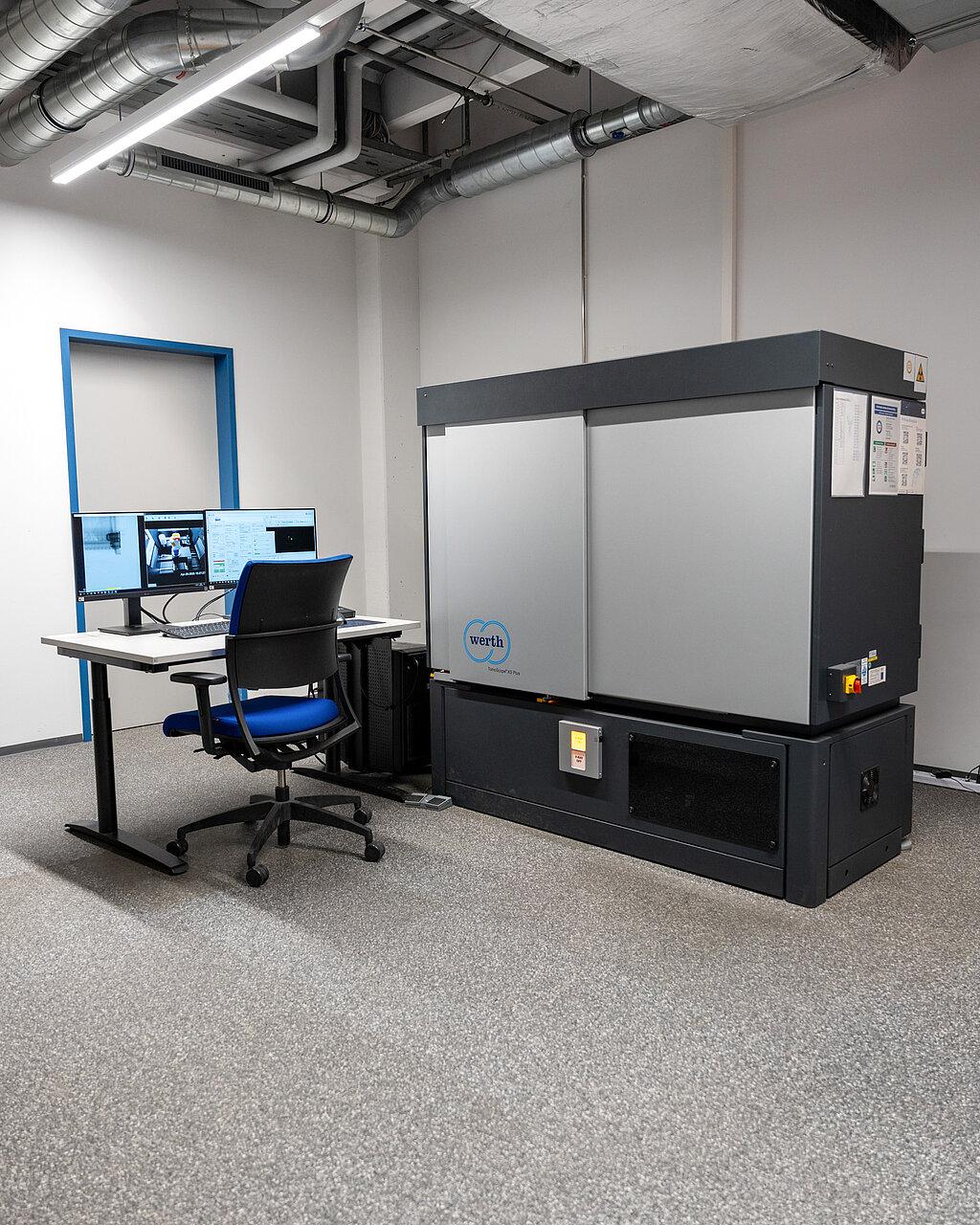
Werth Messtechnik GmbH / TomoScope XS
Test Equipment Number: Q-60-15495
Calibration Frequency / Month: 12 months, maintenance 12 months
Spezification: The system features a tube voltage of up to 200 kV and a power output of 80 watts, enabling highly precise inspections. A 16-inch digital detector with 4 megapixels ensures excellent contrast resolution, while the transmission target with a focal spot size of approximately 1 μm captures even the finest details. The temperature-stabilized radiation protection cabinet ensures consistent performance. The system also offers expansion options for automation, a long-life target, and a workpiece changer to ensure efficient and smooth inspection processes.
Possible Applications: 3D metrology, lunker analyses, wall thickness analyses, target-actual comparson, defect analyses, fiber composite analyses
Special Accessories, Software, Clamping Options: phoenix datos x3D CT acquisition and reconstruction Software, 5 workplaces with VG-StudioMax vor evaluation of the scan data
Comprehensive Documentation for Detailed Analysis
Hirschmann Automotive offers various documentation options for analyzing and visualizing measurement results. These include the standard measurement report (EMPB) and a computed tomography part inspection video, providing detailed views in all axes. A false-color 2D report highlights deviations visually as a screenshot. For the 3D target/actual comparison, a free viewer is provided, which also allows you to review the measurement strategy and individual positions. The computed tomography dataset is available as an STL file.
- visualization
- analyses
- alignment of data records
- measuring instruments
- videos / Animations
- display of analyses & reports
- data import/export
- defect analysis (air pockets, voids, foreign particles)
- porosity analysis
- material testing
- wall thickness analysis
- statement of the complete geometry of the component
- measuring method on 3D digitized data record
- various measuring strategies possible (+ inner contours)
- flexible part and „Bestfit“ alignments possible
- dimensional measurement of parts
- creation of measurement reports (EMPB)
- statement of the complete geometry of the component
- generation of point clouds (voxels) for reconstruction to a 3D model
- target / actual comparison (2D contour plot and 3D possible)
- generation of 3D volume data
- display of deviations from CAD (shrink marks, distortion, etc. of the geometry)
- 100 % statement of the complete geometry of the component
Surface Roughness Measurement
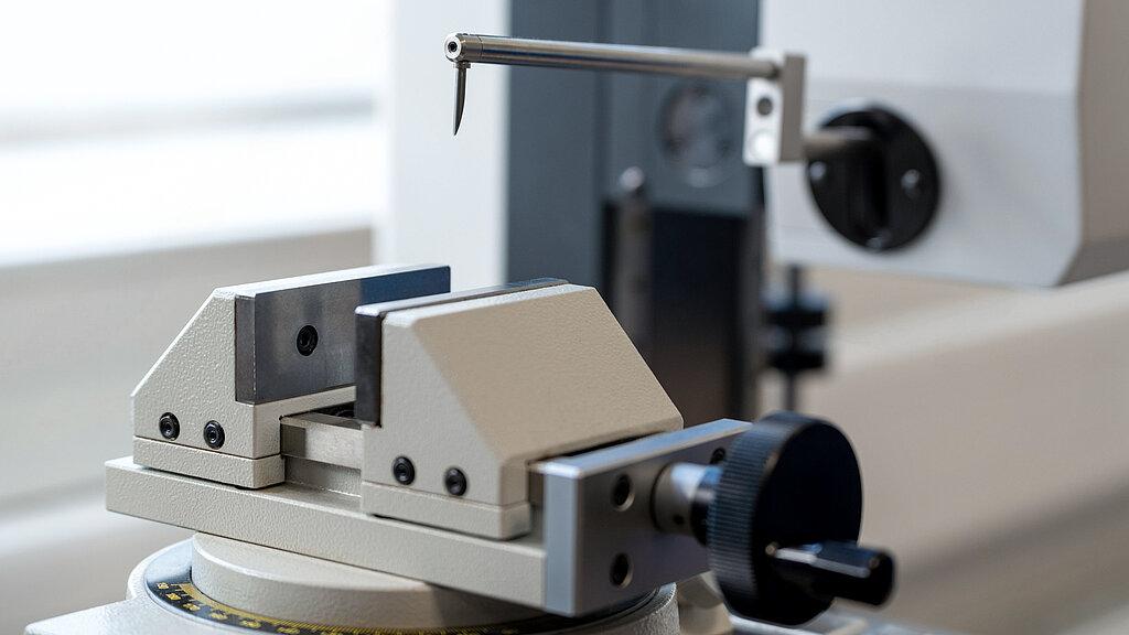
Hirschmann Automotive performs surface roughness measurements in accordance with DIN EN ISO 4288. These evaluations ensure that surface quality is accurately measured and documented according to the required standards.
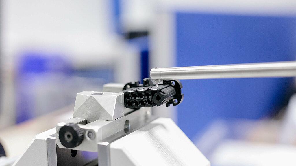
Accurate Contour Measurement for Workpieces
At Hirschmann Automotive, the contours of workpieces are measured two-dimensionally using a contour measuring device. This device features a touch probe that tactically traverses the workpiece to measure points along its contour. The Mitutoyo Formtracer provides a measuring range of 100 mm on the x-axis and 350 mm on the z1-axis.
I want to get in touch
Global Head of Laboratory
